Hydraulic press brakes are a cornerstone of sheet metal fabrication, enabling precise bending across automotive, aerospace and more. If you’ve ever wondered ‘how does a hydraulic press brake work’, this guide explains the core principle, key components and the exact bending sequence—from ram motion to finished part.
Basic Working Principle: Harnessing Hydraulic Power for Bending
So how does a hydraulic press brake work at its core? It relies on pressurised hydraulic fluid (usually oil) feeding cylinders that drive a ram downward. That controlled compression supplies the force to bend sheet metal against a matched punch and die.
Why Hydraulic?
- High Force Output: Hydraulic systems can consistently deliver tons of pressure, suitable for bending thick or high-tensile materials.
- Smooth, Controlled Motion: Operators can adjust fluid flow, pressure levels, and ram speed with precision.
- Load Adaptability: Hydraulics let press brakes maintain full tonnage throughout the bending stroke, ensuring uniform bends and fewer mechanical stress points on the machine.
Key Components of a Hydraulic Press Brake
To answer how a hydraulic press brake works in practice, it helps to know the hardware. These are the key components that control pressure, position and bend accuracy:
- Ram (or Upper Beam)
- The primary moving element: a robust steel structure that descends onto the metal workpiece to create bends.
- Powered by hydraulic cylinders, the ram’s movement is crucial for controlling bend angles.
- Die (and Punch)
- Punch: Attached to the ram, this piece contacts the metal from above. The punch’s shape matches the desired bend (e.g., V-shaped, U-shaped).
- Die: Located on the bed or lower beam, the die receives the workpiece from below. Together, punch and die form the bending channel.
- Hydraulic System
- Oil Reservoir: Stores hydraulic fluid.
- Pump and Valves: Elevates fluid pressure and directs oil flow into or out of cylinders.
- Cylinders: Convert fluid pressure into mechanical force. These are typically mounted on the sides or back of the press brake frame.
- Back Gauge
- An adjustable stop that positions the metal sheet for consistent bending lengths. Operators program the back gauge to the desired dimension so the machine can produce repeatable results.
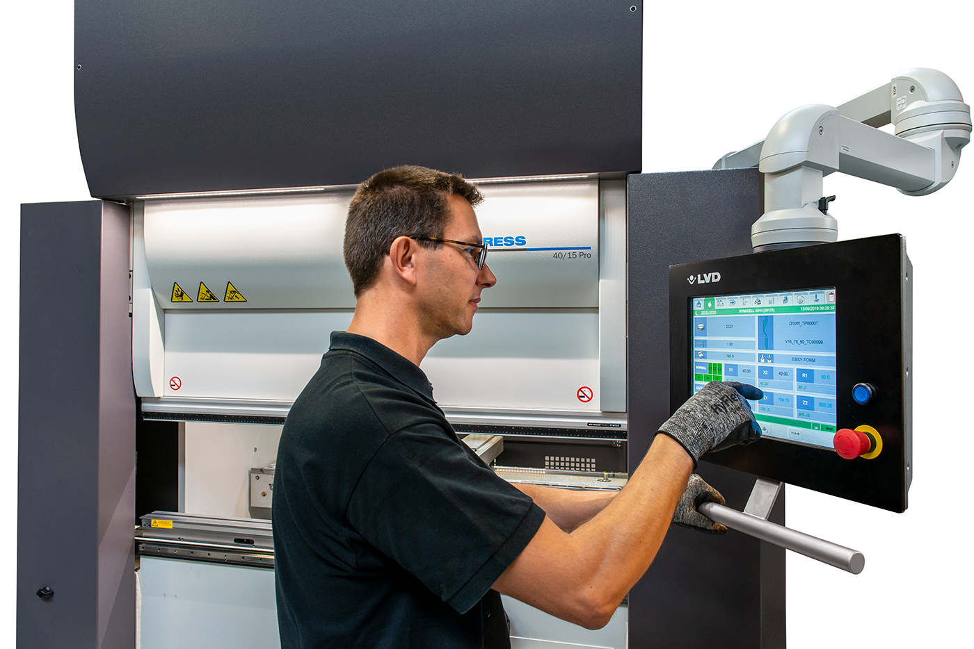
- Control System
- Modern hydraulic press brakes often use CNC or NC controllers, enabling precise stroke control, back gauge positioning, and bend angle calculations.
- Operators input bend angles, material thickness, and other parameters, with the machine automating the rest.
- Bed (or Lower Beam)
- The sturdy, static base that holds the die and supports the bending process. It must handle the full load applied by the ram without flexing beyond tolerance.
Step-by-Step Operation
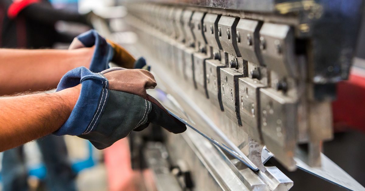
- Positioning the Material
- The operator sets or programs the back gauge to the required distance from the bend line.
- The metal sheet is placed on the bed, flush against the back gauge, ensuring consistent alignment.
- Clamping and Safety Checks
- Hydraulic or mechanical clamping holds the sheet in place, preventing slippage during bending.
- Operators (or the control system) confirm correct punch, die, and bend sequence, verifying the machine’s tonnage and stroke settings.
- Ram Descent
- At the press of a pedal or automatic command, hydraulic cylinders push fluid to move the ram downward.
- The punch contacts the sheet, bending it into the die opening. The bend angle depends on how far the ram travels (stroke depth) and the punch/die geometry.
- Bending and Hold Time
- Once the desired angle is reached, the machine may hold the position briefly, reducing “springback” (where metal tries to revert partially to its original shape).
- For more complex bends, the operator may require multiple steps, repositioning or rotating the metal.
- Ram Return
- After bending, fluid is rerouted (via valves) out of the cylinders, allowing the ram to move upward.
- The operator (or automated conveyor) removes or repositions the workpiece if additional bends are needed.
- Quality Check
- The formed part is measured or visually inspected. If the angle or dimensions deviate, operators adjust parameters in the CNC/NC controller or tweak hydraulic pressure for subsequent bends.
Advantages of Hydraulic Press Brakes
- Precision and Repeatability
- By adjusting pressure and stroke depth, hydraulic systems achieve consistent bends across multiple parts with minimal deviation.
- High Force Capacity
- Unlike mechanical presses limited by a set stroke, hydraulics can maintain maximum tonnage throughout the bending cycle, tackling thicker or harder metals.
- Ease of Use and Automation
- Modern controls let operators store bending programs, auto-calculate angles, and handle complex forming sequences, simplifying training and operation.
- Versatility
- Interchangeable punches and dies accommodate various shapes—from simple 90° bends to multi-step forming processes—catering to diverse metal fabrication demands.
- Controlled Speeds
- Hydraulic flow controls allow slower or more precise ram movement, critical for intricate shapes or delicate materials.
Hydraulic press brakes remain indispensable in sheet metal fabrication for their power, precision, and versatile control over bending angles. By pushing hydraulic fluid through cylinders, these machines generate the substantial, consistent force needed to shape metal with accuracy—an essential advantage in industries where dimensional consistency and structural integrity matter. Understanding the components, operation steps, and advantages of hydraulic press brakes helps technicians and engineers maximise efficiency, produce high-quality bends, and drive innovation in modern manufacturing processes.