
A press brake stands as one of the most powerful tools in metal fabrication, designed specifically for bending sheet and plate metal into precise shapes and angles. Learning how to use a press brake effectively opens doors to countless fabrication possibilities across automotive, aerospace, construction, and electronics industries. The machine harnesses the natural ductility of metals—their ability to deform under pressure while retaining structural integrity—to create bends that would be impossible through manual methods.
Understanding how to use a press brake properly involves more than just operating controls. The process requires knowledge of machine components, safety protocols, and the intricate relationship between force, material properties, and tooling selection. With forces reaching hundreds or thousands of tonnes, even small operational errors can result in damaged parts, broken tooling, or serious injury.
Modern press brakes combine mechanical power with sophisticated control systems, allowing operators to achieve repeatability and precision that manual bending simply cannot match. Whether you’re working with thin aluminum sheets or thick steel plates, mastering press brake operation will dramatically improve both productivity and part quality in your fabrication work.
What makes press brake operation both challenging and rewarding is the blend of technical knowledge and hands-on skill required for success.
Every press brake consists of several key components working in harmony to deliver precise bends. Knowing how each part functions helps operators understand not just how to use, but why certain procedures matter for both safety and quality.
The frame provides the structural foundation for all press brake operations, typically featuring two robust C-shaped side housings connected by upper and lower beams. This design must withstand enormous forces without flexing, as even minor frame distortion affects bending accuracy across the entire work area. The ram, sometimes called the upper beam or slider, serves as the moving force delivery system that drives the punch downward into the workpiece.
Ram movement involves multiple phases during operation—rapid approach, controlled bending speed, and quick return—each requiring precise control for optimal results. The workbench or bed acts as the stationary platform where dies mount securely. Its surface must remain perfectly flat and properly supported to prevent deflection under load, which would compromise bend angles and part quality.
Modern frames often incorporate additional features like front support arms for handling large sheets and integrated storage for tooling accessories. Understanding these structural elements helps operators recognize how machine setup directly impacts bending performance and part consistency.
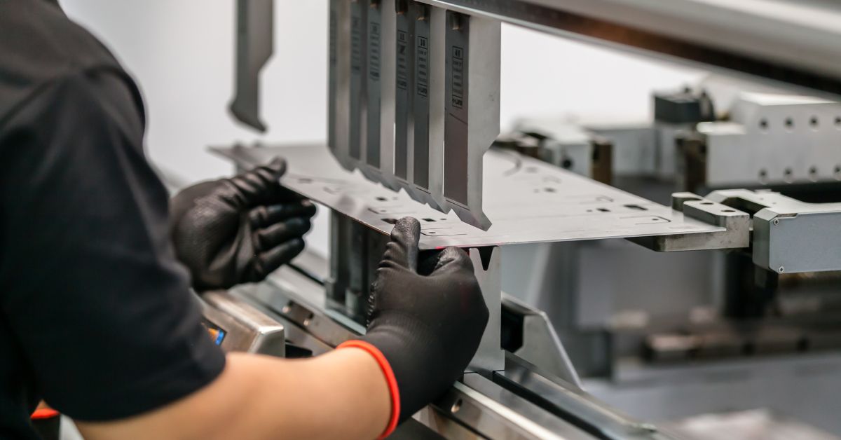
The punch and die combination creates the actual metal forming action in press brake operation. Punches attach to the ram and come in various profiles—sharp for acute angles, radius-shaped for curved bends, or specialized forms for unique applications. Dies mount to the workbench and provide the female portion of the forming setup, with V-dies being most common for general bending work.
Back gauge systems position workpieces accurately relative to the bend line, allowing operators to achieve consistent flange dimensions across multiple parts. Advanced CNC back gauges offer multi-axis positioning capability, enabling complex part geometries through automated sequences. The relationship between these three components—punch geometry, die opening, and back gauge position—determines final part dimensions and quality.
Tooling selection significantly affects how you approach operating a press brake for different materials and applications. Softer materials might require wider die openings to prevent marking, while harder materials need more robust tooling to handle the increased forces involved.
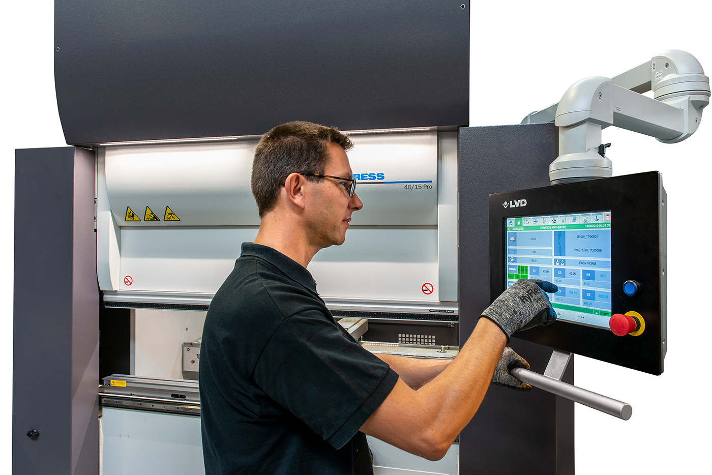
Press brake control systems have evolved from basic manual operations to sophisticated CNC platforms capable of storing hundreds of part programs. These systems manage not only basic functions like ram speed and position but also coordinate back gauge movements, calculate bending forces, and monitor safety device status. Learning how to use a press brake effectively means understanding these control interfaces and programming capabilities.
Safety systems integrate multiple technologies to protect operators from the inherent dangers of high-force metal bending. Light curtains create invisible barriers that immediately stop ram movement if interrupted, while laser guarding systems provide even more precise protection around the tooling area. Two-hand control systems prevent accidental activation by requiring simultaneous button presses, keeping operators’ hands away from pinch points during bending cycles.
Emergency stop buttons scattered throughout the work area allow immediate shutdown from any position around the machine. These safety features work together to create multiple layers of protection, but they require proper maintenance and should never be bypassed or disabled during operation.
Different press brake designs suit various production requirements, material types, and precision needs. Understanding these variations helps fabricators choose equipment that best matches their specific applications and production volumes.
Hydraulic press brakes dominate most fabrication shops due to their versatility and power delivery characteristics. These machines use pressurized hydraulic fluid to drive pistons that move the ram, providing smooth, controllable motion throughout the entire stroke length. This design allows operators to maintain full tonnage capacity regardless of ram position, making hydraulic systems particularly effective for thick material bending and deep forming operations.
The hydraulic system’s inherent overload protection prevents damage from excessive forces through pressure relief valves and accumulator systems. Variable speed control lets operators adjust ram velocity for different bending phases—fast approach, slow forming speed, and quick return—optimizing cycle times while maintaining precision. Modern hydraulic press brakes often incorporate servo-controlled valves for even finer motion control and energy efficiency.
Hydraulic machines typically offer the best balance of power, precision, and cost-effectiveness for most sheet metal fabrication applications. Their ability to handle a wide range of material thicknesses and lengths makes them the preferred choice when learning how to use a press brake across diverse production requirements.
CNC (Computer Numerical Control) press brakes represent the pinnacle of bending automation and precision. While many CNC machines use hydraulic power systems, their defining characteristic lies in the sophisticated computer control that manages all aspects of the bending process. These systems store part programs containing all bending parameters—angles, back gauge positions, ram speeds, and tonnage calculations—enabling one-touch setup for repeat jobs.
Programming CNC press brakes involves inputting material properties, bend sequences, and dimensional requirements through user-friendly interfaces. Advanced systems include bend simulation software that predicts final part geometry and identifies potential collision issues before actual bending begins. This capability significantly reduces setup time and material waste while improving overall productivity.
CNC technology becomes particularly valuable for complex parts requiring multiple bends with tight tolerances. The system’s ability to automatically adjust for springback compensation and coordinate multi-axis back gauge movements makes it possible to produce intricate geometries that would be extremely difficult with manual operation.
Mechanical press brakes use flywheel energy storage and clutch systems to deliver bending force, offering high-speed operation ideal for repetitive production runs. While generally less precise than hydraulic systems, mechanical machines excel in high-volume applications where speed matters more than flexibility. Their simpler design often results in lower maintenance requirements and operating costs.
Pneumatic press brakes utilize compressed air for lighter-duty applications, typically handling thinner materials at lower tonnage levels. These machines offer quick setup times and lower operating costs but lack the force capacity needed for heavy-duty fabrication work. Servo-electric press brakes represent newer technology that combines electric motor drive systems with sophisticated motion control for extremely precise positioning and energy-efficient operation.
Hybrid press brakes attempt to combine the best features of different drive systems, often pairing hydraulic power with electric servo control for optimal performance characteristics. Understanding these variations helps operators choose the right equipment for specific applications and learn how to use a press brake most effectively for their particular needs.
Safe and efficient press brake operation follows a systematic approach that prioritizes both quality and safety at every stage. These procedures form the foundation for consistent results and accident prevention.
Before beginning any bending operation, conduct a thorough inspection of both the machine and work environment. Check the area around the press brake for adequate lighting, clear walkways, and absence of any obstructions that might interfere with material handling or emergency access. Examine electrical connections for damage, hydraulic lines for leaks, and mechanical components for proper alignment and lubrication.
Test all control functions including foot pedals, push buttons, and emergency stops to verify proper operation. Inspect safety devices such as light curtains and laser guards for cleanliness and proper positioning—dirty or misaligned sensors can cause unexpected machine behavior. Check that all guards and barriers remain securely in place and haven’t been modified or bypassed.
Verify that tooling is clean, properly installed, and appropriate for the planned work. Examine punch and die surfaces for damage, wear, or debris that could affect bend quality. Confirm that back gauge fingers are correctly positioned and that any front support arms are properly adjusted for the material size being processed.
Review the work order and material specifications to understand bending requirements, tolerances, and any special considerations. This preparation phase sets the foundation for successful operation and helps prevent common mistakes that lead to scrapped parts or safety incidents.
Press brake start-up procedures vary by manufacturer but generally follow a logical sequence designed to verify system integrity before operation begins. Activate main power at the isolation switch, which typically energizes the control system and allows initial diagnostics to run. Many machines perform automatic system checks during this phase, verifying that safety devices function properly and hydraulic systems maintain correct pressure.
Engage the hydraulic system using the appropriate controls, often involving a two-stage process that first starts circulation pumps followed by main system pressurization. The machine may require an overrun test using the foot pedal to verify that safety systems can stop ram movement within specified distances. This test demonstrates that stopping performance meets safety requirements.
Set or verify the mute point, which allows safety devices to temporarily deactivate during the final slow-speed portion of the bending cycle. This typically involves placing a sample piece on the die so the system can calculate proper thickness compensation. Reset this setting whenever changing materials or tooling to maintain safety system effectiveness.
For CNC-equipped machines, input part programs containing bend angles, back gauge positions, material specifications, and other parameters. Double-check all entries against work order requirements and use simulation functions when available to verify program correctness before processing actual parts.
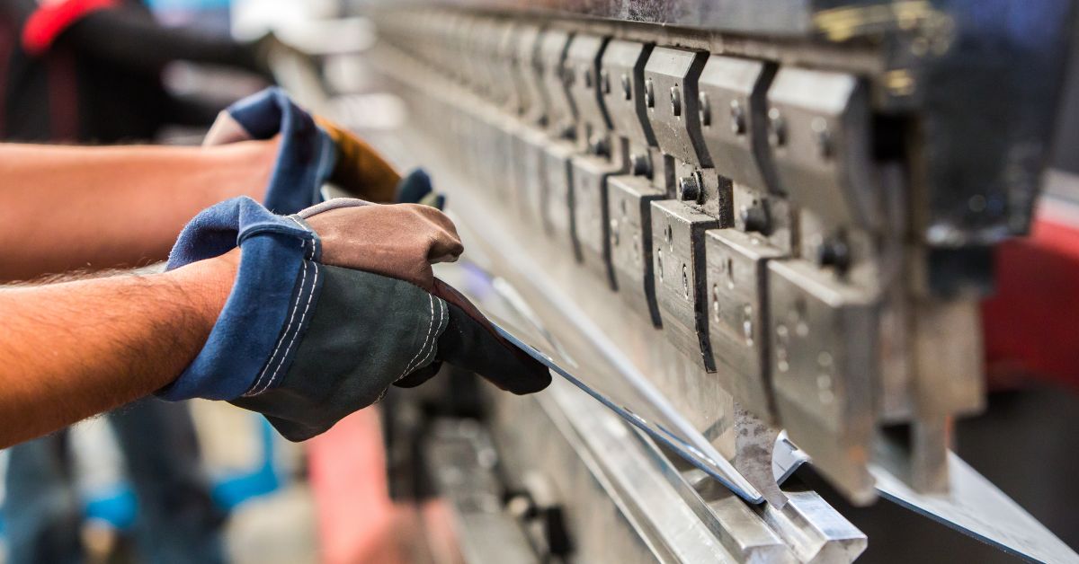
Position the workpiece against the back gauge fingers, taking care to align the bend line properly with the tooling centerline. For large or heavy sheets, use front support arms or seek assistance to prevent material movement during positioning. Activate any clamping devices to secure the workpiece before beginning the bending cycle.
Initiate the bending cycle using the foot pedal or programmed automatic sequence. The ram will descend rapidly to the mute point, where it automatically shifts to slow speed for the final forming portion of the stroke. Keep hands and other body parts clear of the bending area during this phase—even slow-speed movement involves tremendous force that can cause severe injury.
Some programs include a hold period where the machine maintains pressure at the bottom of the stroke to minimize springback effects. After the programmed cycle completes, the ram returns automatically to its starting position. Remove the bent part carefully and inspect dimensions against specification requirements.
Measure bend angles using appropriate gauges and check flange lengths with rulers or calipers. Compare results against tolerance requirements and adjust machine parameters if necessary before continuing production. This quality control step prevents producing entire batches of out-of-specification parts.
Complete all bending operations and remove workpieces, scraps, and tooling from the machine area. Power down systems in reverse order of startup, typically involving hydraulic system shutdown followed by main power disconnection. Store the foot control and any portable accessories in designated locations to prevent damage or loss.
Clean the work area of metal chips, oil spills, and other debris that could create safety hazards. Return any shared tooling or measuring equipment to proper storage locations. Document any unusual observations or maintenance needs in appropriate logbooks for follow-up action.
Proper shutdown procedures help prevent equipment damage and prepare the machine for the next operator or shift. Taking time for good housekeeping practices contributes to overall shop safety and efficiency.
Tooling selection and management directly impact both bend quality and production efficiency. Understanding the relationship between tooling characteristics and material properties helps operators achieve optimal results while maximizing tool life.
Material thickness serves as the primary factor in tooling selection, with the general rule that V-die opening should be 6 to 12 times material thickness, with 8 times being most common. Thicker materials require wider die openings to accommodate the larger bend radius that develops naturally during forming. Material type also influences tooling choice—stainless steel’s work-hardening characteristics might require different punch profiles compared to mild steel of similar thickness.
Bend angle requirements determine punch geometry, with sharp-tip punches used for acute angles and radius punches for curved forms. The bending method—air bending, bottoming, or coining—affects both punch and die design. Air bending offers the most flexibility since one set of tooling can produce multiple angles, while bottoming and coining require specific tooling geometry for each desired result.
Machine tonnage capacity sets limits on tooling size and application range. Calculate required bending force using standard formulas that consider material properties, thickness, bend length, and die opening. Choose tooling rated for these calculated loads with appropriate safety margins to prevent damage during operation.
Tooling material and hardness significantly affect service life and bend quality. Most professional tooling uses hardened tool steel (typically around 55-60 HRC) for durability, while some specialized applications might require carbide inserts or other exotic materials for extreme wear resistance.
Safe tooling changes require complete machine shutdown and power isolation to prevent accidental activation during the changeover process. Lower the ram to support any mounted punches before loosening clamps or mounting hardware. Remove used tooling carefully, watching for sharp edges and heavy components that might cause injury if dropped.
When installing new punches, position them carefully in the mounting system and secure lightly before applying full clamping force. Verify that punch alignment matches die centerlines to prevent damage during operation. For die changes, use any mechanical assists provided by the machine manufacturer to handle heavy V-blocks safely.
Calculate proper V-die openings based on material thickness and verify settings before resuming operation. Many modern machines include tooling databases that automatically suggest appropriate settings based on material specifications and desired bend parameters. Take advantage of these features to reduce setup time and prevent tooling damage from incorrect applications.
Document tooling changes and settings in production records for future reference. This documentation helps maintain consistency between shifts and provides valuable data for process improvement efforts.
GWB Machine Tools provides comprehensive tooling solutions as the exclusive Australian distributor for LVD press brake tooling systems. Their inventory includes standard punches and dies for general fabrication work, specialized STONE radius tooling for forming applications, and innovative vertical removable tooling designed for faster, safer changeovers.
Local stocking of popular tooling lines reduces delivery times and keeps production running smoothly. GWB’s technical expertise helps customers select optimal tooling for specific applications while their direct relationship with LVD enables custom tooling solutions for unique fabrication challenges. This combination of product availability and technical support makes GWB Machine Tools the preferred partner for Australian fabricators seeking reliable tooling performance.
Press brake safety requires constant attention to potential hazards and strict adherence to protective procedures. The combination of high forces, sharp tooling, and heavy materials creates multiple injury risks that proper safety practices help minimize.
Safety glasses protect eyes from metal chips and debris generated during bending operations. Choose wrap-around styles that provide side protection and impact-resistant lenses appropriate for industrial environments. Protective gloves guard hands from sharp material edges but should be removed when working near moving machinery to prevent entanglement hazards.
Safety footwear with steel toes and puncture-resistant soles protects feet from falling objects and sharp debris. High-visibility clothing improves operator visibility around the machine while long sleeves and pants protect skin from metal edges and hydraulic fluid. Avoid loose clothing, jewelry, or long hair that might catch in moving machinery.
Hearing protection becomes necessary in noisy shop environments where multiple machines operate simultaneously. Select appropriate protection based on measured noise levels and duration of exposure. Some facilities require hearing protection in all production areas regardless of individual machine noise levels.
Light curtains create invisible barriers that immediately stop ram movement when interrupted, protecting operators who need to work near the bending area. These systems require regular cleaning and calibration to maintain proper sensitivity and response times. Never attempt to defeat or bypass light curtain protection—their purpose is preventing serious crush injuries.
Laser guarding systems provide even more precise protection by monitoring smaller areas directly around the tooling. These systems can distinguish between workpieces and human body parts, allowing closer approach while maintaining safety. Two-hand controls prevent accidental machine activation by requiring simultaneous operation of separate switches located beyond reach of the danger zone.
Emergency stop buttons located around the machine perimeter allow immediate shutdown from any position. Test these controls regularly and keep access paths clear at all times. Physical barriers and warning signs help keep untrained personnel away from hazardous areas during operation.
Lockout/tagout procedures prevent accidental machine startup during maintenance or tooling changes. Follow established procedures for isolating all energy sources and use personal locks and tags to maintain control until work is completed.
Only trained, authorized operators should run press brakes, with initial training including both theoretical knowledge and supervised hands-on experience. Ongoing training updates help maintain skills and introduce new safety concepts as they develop. Maintain awareness of changing conditions that might affect safety, such as material handling requirements or production schedule pressures.
Material handling presents significant injury risks due to sharp edges, awkward shapes, and heavy weights. Use appropriate lifting techniques and seek assistance when handling large sheets that exceed safe lifting limits for individual operators. Plan material movement to minimize handling and reduce fatigue that can lead to accidents.
Keep work areas clean and well-organized to prevent tripping hazards and allow quick access to emergency controls. Good housekeeping also prevents small debris from interfering with safety device operation or causing slip hazards around the machine.
Stay alert to crush points, pinch zones, and other hazardous areas throughout the bending cycle. Even experienced operators can become complacent about familiar hazards, making conscious hazard awareness an ongoing responsibility rather than a one-time training topic.
Recognizing and preventing common press brake mistakes helps maintain both quality standards and operational efficiency. Many problems result from rushing through procedures or skipping verification steps that seem routine but serve important purposes.
Skipping pre-operational inspections creates opportunities for problems to develop into serious issues. Misaligned dies produce inconsistent bend angles across part length, while incorrect back gauge settings result in wrong flange dimensions that may not be discovered until entire production runs are completed. Malfunctioning safety devices present injury risks that proper inspection would identify before operation begins.
Improper machine setup affects both part quality and equipment reliability. Incorrect ram height adjustments can cause tooling damage from excessive penetration, while wrong tonnage calculations might overload the machine or produce inadequate bends. Take time to verify all settings against work order requirements and double-check calculations before beginning production.
Tooling alignment problems cause premature wear and poor bend quality. Check that punch and die centerlines align properly and that mounting surfaces are clean and free from debris. Small alignment errors multiply across long bends, creating parts that won’t meet assembly requirements.
Using wrong tooling for specific applications leads to poor results and potential equipment damage. Attempting to bottom bend when air bending is appropriate can overload both machine and tooling while producing inconsistent results. Consult tooling charts and material specifications to select appropriate combinations for each job.
Material grain direction affects bend quality and part strength, particularly with rolled materials that exhibit directional properties. Bending parallel to grain direction can cause cracking in brittle materials, while perpendicular bending typically produces stronger, more consistent results. Consider material orientation when planning bend sequences and part layouts.
Ignoring material springback characteristics results in parts that don’t meet angle specifications. Different materials and thicknesses exhibit varying amounts of springback that must be compensated through overbending. Develop springback data for commonly used materials and adjust programs accordingly.
CNC programming errors can ruin entire production runs before problems are discovered. Verify all program parameters against job requirements and use simulation features when available to check for obvious errors. Test programs with sample pieces before committing to full production quantities.
Tonnage miscalculations can damage equipment or produce inadequate bends. Use established formulas or software tools to calculate required forces based on material properties, bend geometry, and tooling selection. Include appropriate safety margins but avoid excessive overbending that wastes energy and stresses equipment unnecessarily.
Failing to account for material variation can cause problems even with correct programs. Material thickness, strength, and surface condition can vary between lots, requiring program adjustments to maintain consistent results. Monitor first-piece quality closely and adjust parameters as needed throughout production runs.
GWB Machine Tools stands ready to support Australian and New Zealand fabricators with comprehensive press brake solutions that go far beyond equipment sales. As the exclusive distributor for LVD press brake technology, GWB combines world-class machinery with decades of local engineering expertise to deliver customized solutions that address specific production challenges.
Their technical support team understands how to use a press brake effectively across diverse applications, from simple brackets to complex aerospace components. This knowledge translates into faster installations, more effective operator training, and ongoing support that keeps production running smoothly. With genuine LVD spare parts stocked locally, downtime stays minimal even when unexpected maintenance needs arise.
GWB’s commitment extends beyond initial machine delivery to long-term partnerships that adapt to changing fabrication requirements. Whether upgrading existing equipment, expanding production capacity, or solving specific technical challenges, GWB Machine Tools provides the expertise and support that Australian fabricators need to remain competitive in demanding markets.
The combination of premium LVD technology and GWB’s local support creates a compelling value proposition for fabricators serious about press brake performance and reliability.
Learning how to use a press brake effectively combines technical knowledge with disciplined safety practices and attention to detail. Success depends on understanding machine components, following systematic procedures, selecting appropriate tooling, and maintaining constant awareness of potential hazards. The investment in proper training and procedural discipline pays dividends through improved part quality, reduced downtime, and accident-free operations.
Modern press brakes offer remarkable capabilities for precise metal forming, but realizing their full potential requires skilled operators who understand both the machines and the materials they process. By following the guidelines presented in this guide and maintaining a commitment to continuous improvement, operators can achieve the consistency and efficiency that characterizes professional metal fabrication operations.
Remember that press brake operation involves ongoing learning as new materials, applications, and technologies continue to evolve. Stay current with industry developments and maintain the safety-first mindset that protects both people and equipment in demanding production environments.
Press brakes and punch presses are central to most fabrication workshops across Australia. They deliver precision and productivity, but they also introduce serious risks if not managed correctly. Clear and practical press brake safety tips are essential for maintaining a safe working environment without slowing production. When safety becomes part of daily operations rather than … Press Brake Safety Tips Every Aussie Workshop Needs
Short lead times, tight margins and labour shortages continue to challenge sheet metal workshops across Australia and New Zealand. Every inefficiency in production adds cost, especially when machines are not being used to their full capability. This is why the discussion around laser cutting vs punching remains so important. Rather than choosing one process over … Laser Cutting vs Punching: Choosing the Right Mix
Rising labour costs, a shrinking pool of skilled tradespeople, tighter tolerances, and faster customer expectations are reshaping metal fabrication across Australia and New Zealand. Many workshops have pushed manual processes as far as they can. Overtime and additional staff no longer deliver the gains they once did. Automation systems for fabrication now offer a practical … Automation Systems for Fabrication